Frequency TranslatorsCharacteristics that affect the performance of frequency translators have been enhanced to include minimization of PM-to-AM conversion, use of high slew rate drivers and optimizing phase shift linearity with applied signal. As a result, carrier and sideband suppression levels of over 25 and 20 dB are obtained across the entire frequency range, which ranges from 200 MHz to 22 GHz in up to 9:1 bandwidths. Narrowband models available from 22.0 GHz to 35.0 GHz with 10% bandwidth. |
 |
Frequency Ranges: From 200 MHz to 22 GHz, up to 9:1 bandwidths available as well as any optimization. Narrowband models available from 22.0 GHz to 35.0 GHz with 10% bandwidth.
TTL Compatible Logic: Binary logic Digital-to-Analog converter with 8 inputs; Logic ‘1’ / BIT = 256 discrete phase shifts with a 1.41 degree resolution (LSB) or all Logic ‘0’ = 0° reference state. Up to 12 BIT resolution available upon request.
Optional Models: Analog Voltage Controlled models and Dual Function models available with selectable input for either translator or phase shifter operations.
High Speed Switching: Frequency Translators listed are measured from any set value to any set value.
Translation Rate: From 0 to 500 kHz, the carrier suppression is 25 dB and sideband suppression is 20 dB minimum.
|
Translation Rates |
||
|
Frequency (GHz) |
Carrier Suppression (dB) |
Side Band Suppression (dB) |
|
2.0-3.0 |
-18 |
-22 |
|
3.0-14.0 |
-20 |
|
|
14.0-18.0 |
-18 |
|
Low DC Power Consumption: Frequency Translators require ±12 to ±15 VDC @ ±100 mA.
Stable Phase Shifts: Variation vs. temperature is typically ±0.17° & ±0.035 dB / degrees C from -10° to +65° for 500 ƞSec models. Slower models have better temperature coefficients, please consult the factory.
Operating Temperature Range: Standard models include temperature compensation in a range from -10° to +65° C. For more severe environments, please consult the factory.
High RF Power Handling: For power levels greater than listed, please consult the factory.
Standard Interfaces: RF port connectors are ‘SMA’ female per MIL-C-39012. Please consult the factory for additional options.
Life Time Integrity: Frequency Translators can be designed to meet MIL-E-16400, Range 1 and MIL-E-5400, Class 2 environments operating within the -55° to +85° temperature range.
Low Phase Noise Option: Offers a typical performance of -132 dBc/Hz @ 10 kHz offsets. Requires ±5 VDC (<2%) @ ±100 mA low noise regulated supplies and user supplied latch command for inputs. Please specify when ordering.
|
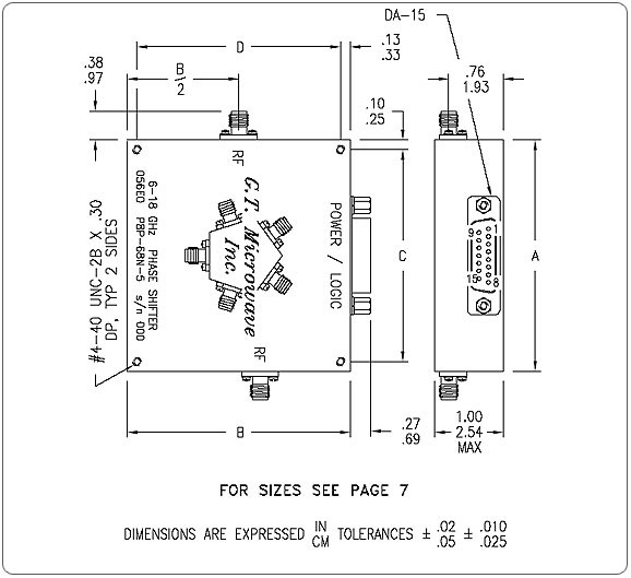
Outline Sizes |
||||
|
Size Reference |
‘A’ Dimension IN/CM |
‘B’ Dimension IN/CM |
‘C’ Dimension IN/CM |
‘D’ Dimension IN/CM |
|
1 |
4.95/12.57 |
3.38/8.58 |
4.75/12.07 |
3.13/7.94 |
|
2 |
3.25/8.26 |
3.25/8.26 |
3.05/7.75 |
3.00/7.62 |
|
3 |
3.00/7.62 |
3.00/7.62 |
2.80/7.12 |
2.75/6.99 |
|
4 |
4.25/10.80 |
3.50/8.89 |
3.25/8.26 |
3.25/8.26 |
|
5 |
5.00/12.70 |
5.00/12.70 |
4.80/12.20 |
4.75/12.07 |
|
6 |
5.38/13.65 |
4.50/11.43 |
5.18/13.15 |
4.25/10.80 |
Outline Diagram
|
Power/Logic Connections |
||||
|
Number of BITs |
Logic PIN Assignments |
+15 V PIN |
-15 V PIN |
Ground PIN |
|
8 |
LSB @ 1 to MSB @ 8 |
13 |
14 |
15 |
|
10 |
LSB @ 1 to MSB @ 10 |
13 |
14 |
15 |
|
12 |
LSB @ 1 to MSB @ 12 |
13 |
14 |
15 |
|
All unused PINs have no internal connections |
||||
For substantial improvement in performance, ask for optimized narrowband models.
|
Electrical Specifications for 500 ηSec Digitally Controlled Frequency Translators |
|||||||
|
Model Number |
Frequency Range (GHz) |
Phase Error |
Amplitude Translation Variation |
Insertion Loss (dB) |
VSWR |
RF Input Power CW/Max (dBm) |
Size Reference |
|
T*P-18A-5 |
0.2-0.4 |
±10°
|
1.0 dB to 200 kHz
Or
3.0 dB to 500 kHz |
11.0 |
1.6:1 |
0/+30 |
5 |
|
T*P-28A-5 |
0.3-0.6 |
1 |
|||||
|
T*P-39A-5 |
0.5-2.0 |
13.0 |
1.7:1 |
+5/+30 |
|||
|
T*P-38A-5 |
1.0-3.0 |
||||||
|
T*P-49A-5 |
1.0-4.0 |
±15.0° |
1.8:1 |
6 |
|||
|
T*P-48A-5 |
2.0-6.0 |
±10° |
11.0 |
+10/+30 |
2 |
||
|
T*P-58A-5 |
4.0-12.0 |
12.0 |
|||||
|
T*P-68A-5 |
6.0-18.0 |
1.9:1 |
+15/+30 |
3 |
|||
|
T*P-69A-5 |
2.0-18.0 |
±20° |
16.0 |
2.2:1 |
+10/+30 |
4 |
|
|
T*P-84A-5 |
16.0-22.0 |
±15° |
2.0:1 |
+15/+30 |
3 |
||
*T5P = 5 BITs, T6P = 6 BITs, T7P = 7 BITs, T8P = 8 BITs, T9P = 9 BITs, T0P = 10 BITs, T1P = 11 BITs, T2P = 12 BITs
|
Electrical Specifications for 1.0 µSec, High Power, Digitally Controlled Frequency Translators |
|||||||
|
Model Number |
Frequency Range (GHz) |
Phase Error |
Amplitude Translation Variation |
Insertion Loss (dB) |
VSWR |
RF Input Power CW/Max (dBm) |
Size Reference |
|
T*P-18A-1 |
0.2-0.4 |
±10°
|
1.0 dB to 200 kHz
Or
3.0 dB to 500 kHz |
11.0 |
1.6:1 |
+10/+30 |
5 |
|
T*P-28A-1 |
0.3-0.6 |
1 |
|||||
|
T*P-39A-1 |
0.5-2.0 |
13.0 |
1.7:1 |
+15/+30 |
|||
|
T*P-38A-1 |
1.0-3.0 |
||||||
|
T*P-49A-1 |
1.0-4.0 |
±15.0° |
1.8:1 |
6 |
|||
|
T*P-48A-1 |
2.0-6.0 |
±10° |
11.0 |
+23/+30 |
2 |
||
|
T*P-58A-1 |
4.0-12.0 |
12.0 |
|||||
|
T*P-68A-1 |
6.0-18.0 |
1.9:1 |
+25/+30 |
3 |
|||
|
T*P-69A-1 |
2.0-18.0 |
±20° |
16.0 |
2.2:1 |
+23/+30 |
4 |
|
|
T*P-84A-1 |
16.0-22.0 |
±15° |
2.0:1 |
+25/+30 |
3 |
||
*T5P = 5 BITs, T6P = 6 BITs, T7P = 7 BITs, T8P = 8 BITs, T9P = 9 BITs, T0P = 10 BITs, T1P = 11 BITs, T2P = 12 BITs