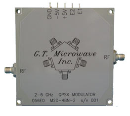
Quad-Phase (QPSK) ModulatorsProduces up to 9:1 bandwidths from 200 MHz to 22 GHz and options that include ultra-broadband, optimized narrowband, and sub-assembly integration. Unit-to-unit phase and amplitude matching available along with bi-directional variable phase characteristics from one port to another. Control options including solder pins or a Multi-Pin Connector. Narrowband models available from 22.0 GHz to 35.0 GHz with 10% bandwidth. |
 |
Frequency Ranges: From 200 MHz to 22 GHz, up to 9:1 bandwidths available as well as any optimization. Narrowband models available from 22.0 GHz to 35.0 GHz with 10% bandwidth.
TTL Compatible Logic: 2 BIT binary logic:
| E1 | E2 | Output |
| 0 | 0 | 0° Ref |
| 1 | 0 | +270° |
| 1 | 1 | +180° |
| 0 | 1 | +90° |
High Speed Switching: QPSK Modulators listed are measured from 50% TTL to 10% / 90% RF from any set value to any set value.
DC Power Consumption: QPSK Modulators require ±5 VDC @ ±100 mA.
Operating Temperature Range: Standard models include temperature compensation in a range from 0° to +50° C. For more severe environments, please consult the factory.
High RF Power Handling: For power levels greater than listed, please consult the factory.
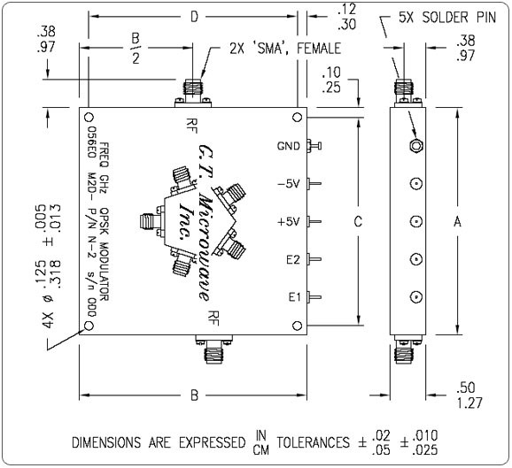
Standard Interfaces: RF port connectors are ‘SMA’ female per MIL-C-39012. DC/Logic connections are solder terminals. Please consult the factory for additional options.
Matched Phase & Amplitude: Models listed can be matched unit-to-unit. Please consult the factory.
|
Outline Sizes |
||||
|
Size Reference |
‘A’ Dimension IN/CM |
‘B’ Dimension IN/CM |
‘C’ Dimension IN/CM |
‘D’ Dimension IN/CM |
|
1 |
4.95/12.57 |
3.38/8.58 |
4.75/12.07 |
3.13/7.94 |
|
2 |
3.25/8.26 |
3.25/8.26 |
3.05/7.75 |
3.00/7.62 |
|
3 |
3.00/7.62 |
3.00/7.62 |
2.80/7.11 |
2.75/6.99 |
|
4 |
4.25/10.80 |
3.50/8.89 |
3.25/8.26 |
3.25/8.26 |
|
5 |
1.60/4.06 |
2.00/5.08 |
1.40/3.56 |
1.75/4.45 |
|
6 |
5.38/13.65 |
4.50/11.43 |
5.13/13.02 |
4.25/10.80 |
Outline Diagram
For substantial improvement in performance, ask for optimized narrowband models.
|
Electrical Specifications for QPSK Modulators |
||||||||
|
Model Number |
Frequency Range (GHz) |
Phase Error |
Amplitude Balance (dB) |
Insertion Loss (dB) |
VSWR |
Switching Speed (ƞSec) |
RF Power (dBm) CW/Max |
Size Reference |
|
M2D-39N-2 |
0.5-2.0 |
±10.0° |
±1.0 |
7.0 |
1.75:1 |
100 |
27/37 |
1 |
|
M2D-38N-2 |
1.0-3.0 |
|||||||
|
M2D-49N-2 |
1.0-4.0 |
±15.0° |
±2.5 |
10.0 |
1.80:1 |
6 |
||
|
M2D-48N-2 |
2.0-6.0 |
±10.0° |
±1.0 |
6.0 |
1.75:1 |
2 |
||
|
M2D-68N-2 |
6.0-18.0 |
8.0 |
3 |
|||||
|
M2D-69N-2 |
2.0-18.0 |
±20.0° |
±2.0 |
11.0 |
2.00:1 |
4 |
||
|
M2D-84N-2 |
16.0-22.0 |
5 |
||||||